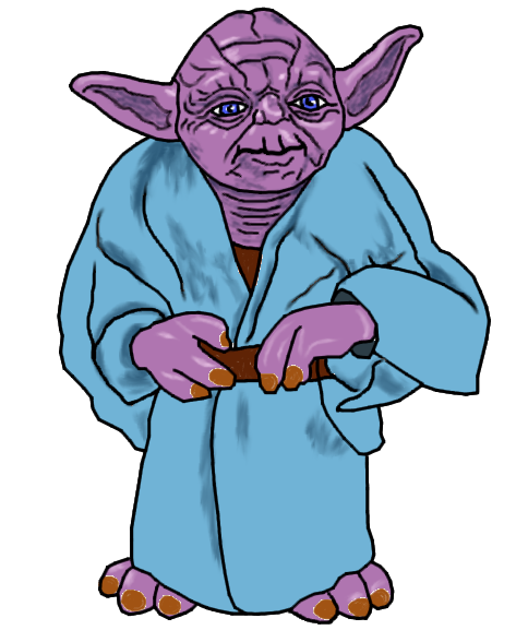
Download the file zodaOutline.blend and rename it zoda.blend. Open it in Blender.
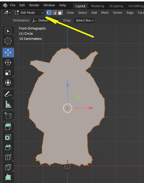
If the creature's outline is not selected, right-click on it to select it. Then from the toolbar above the editing area, switch from Object Mode to Edit Mode (see yellow arrow below). You should see all the control points of the object in orange (selected). If they are not, hit A to select them.
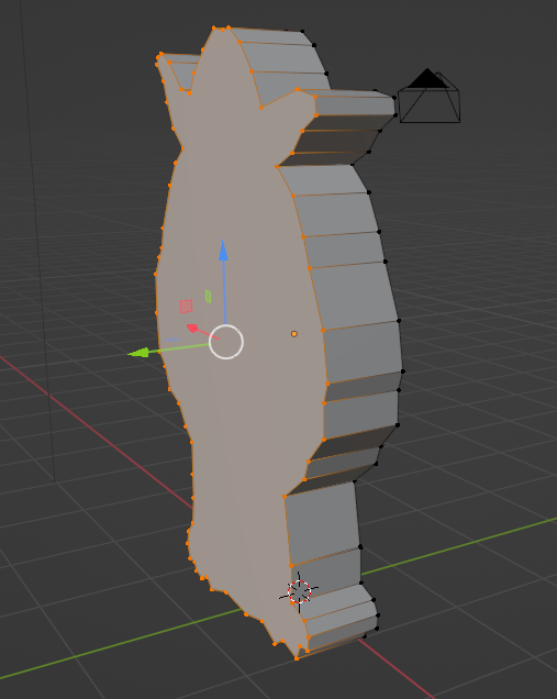
Switch to the Left view from the View menu. Make sure that it says Left Ortho at the top left of the editing area. If it doesn't, then from the View menu, choose View Persp/Ortho. Hit E to extrude the surface, then pull it to the left to give it some depth. Here is an example of the result where the view is rotated a little.
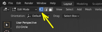
Switch the view to Front Ortho. In the same toolbar as the Edit Mode, make sure that out of the 3 buttons for selecting vertices, edges, or faces, to the right of Edit Mode, the Vertex one is selected:
Hit A to deselect everything. Zoom in on the face of the creature. Let's add some edges to mark out the creature's chin first. Click in the left vertical toolbar on the Knife tool (you may have to double-click on it). Then click to select the point marking the top of the neck on the left side. Then moving to the other side, click to select the point at the base of the right ear. Then hit Enter to commit the cut.
Now create two more cuts, from a point on the new edge a bit to the inside, where the lower corner of the ear would be, towards the top intersection of the ear with the face. Hit Enter after each of them. Then click on the Move tool in the left toolbar (we're done with the knife).
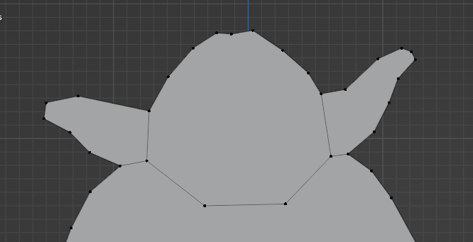
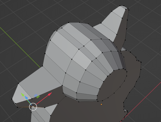
Switch to Edge selection, then select the edge where the chin will be. Then hit Ctrl-R to divide it. Move the mouse pointer over the edge, then scroll once to increase the number of cuts to 2.
Click outside the object to deselect the points. Then select the two points in the middle (chin) and move them down towards where the bottom of the face might be, like below.
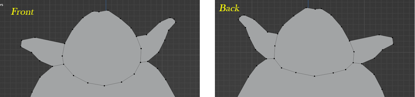
Repeat the procedure on the other side (Back), but with a smaller dip of the curve because there is no chin in the back. If you like finer details, you can divide some of the created edges in two and then adjust the middle points for a rounder result, such as the following:
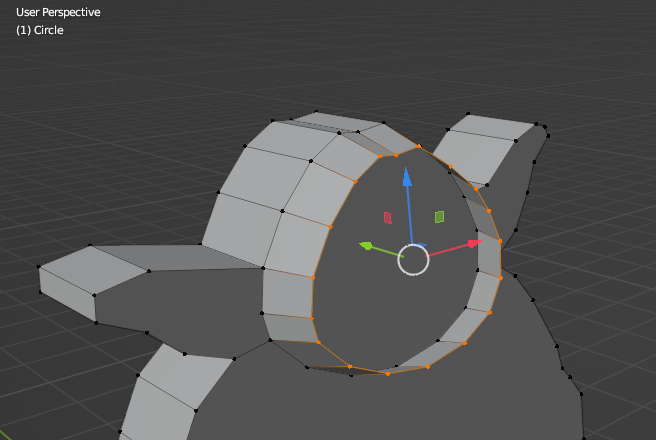
Switch to the Front view and deselect everything. Then hit B to select points in a box and use it to select only the points of the face. Start from above and to the left of the face and left-click and drag the selection to below and to the right of the face. If any other points are selected, unselect them with shift-click, and similarly if any points are missing. Then switch to the left view, hit E to extrude, hit Y to constrain it to the Y axis, then pull it to the right by some amount. Switch back to the front view and hit S to scale it. Shrink the polygon down a little. Here is the result in a rotated view.
Without deselecting the points, extrude them again by a similar amount, then scale them down a bit more than before. After that, hit F to fill out the void with a face. Deselect all the points, then repeat the procedure on the back face, going a bit less forward during the extrusion.
Switch to the Top View and move the points at the top of the ears much closer together to make the ears pointed. Use the green arrow to move the points more easily. Then adjust the intermediate points to create a smoother transition. Here is an example of the effect:
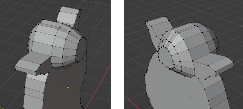
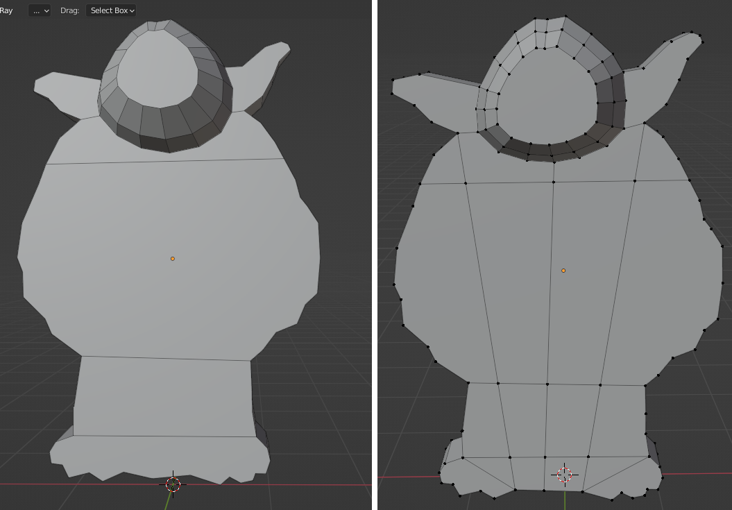
Switch to the Front View, and switch the selection mode to Face. In the vertical toolbar on the left side, click on the Knife tool. Use it to cut an edge across the body, around the shoulders and a little below the chin. You click to select the first point of the cut, click to select the second one, and then right-click to end the cut. Repeat the operation to connect the two points where the sleeves end, and at the bottom of the robe, like in the left image below. When you are done with the cuts, hit Enter to finish the operation.
Using the knife again, cut a line from the point in the center bottom of the model up to the point in the middle of the chin. Then cut to connect the interior of the feet with the bottom of the ears like in the right image below. Add two lines for the feet, like in the image.
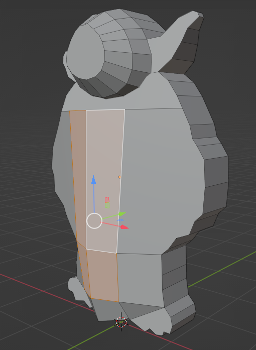
Select the four faces in the middle of the body, that you can see below. Switch to the left view, then pull those forward by some amount. Switch to Edge mode, then select the vertical edges in the center of the body, and pull them forward a little more. The goal is to make the front of the body a bit rounder, like in the image below:
Repeat the procedure for the back side.
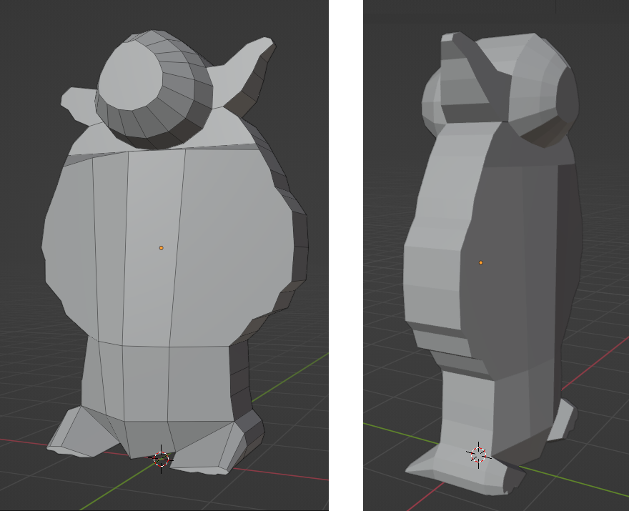
Switching back to the front, in Face mode, select the two faces at the bottom representing the feet. Switch to the left view and extrude them over Y a bit further out than the front of the body. Switch back to the front view and scale the extruded faces over Z by a good amount. Then switch back to the Left view and pull them down, but no further than the bottom of the body. Repeat the operation in the back with a much smaller extrusion , a general scale, and no vertical move of the resulting faces.
Below is an example of the result. Once this done, you can switch back from Edit Mode to Object Mode, as seen on the right below.
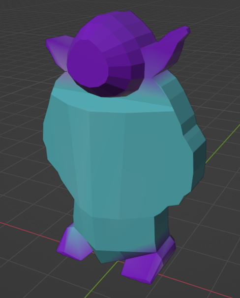
Finally, from Object Mode switch to Vertex Paint mode. Choose a purple color in the color selector on the top left and pain the head and feet of the creature. Then select a light blue color and paint the rest of the body. You can paint the back of the head a bit darker to emphasize the face. Here is an example of painted object:
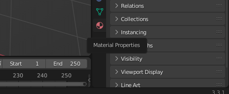
Switch back to Object Mode. Click on the Material Properties button in the vertical toolbar on the right side of the window:
Add a new material to this object. You can leave the default options for now. Then click on the Render Properties and switch the Renderer to Cycles (for some reason, it seems that the Evee renderer doesn't deal well with vertex colors).
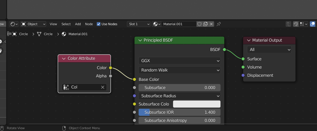
Now click on Shading at the top of the window and zoom in on the lower part of the window to see it better. In this panel, you can link different things into the way the color is rendered. Click Add to add a new node, choose Color Attribute from Input. At the bottom of this node, click on the text box and select Col or whatever option you see there (this is the name of the vertex paint). Then create a link from the Color of this node to the Base Color of the material, as you can see below.
In the top right corner of the window, click on Viewport Shading: Preview or Render. Now the colors you assigned to the vertices should appear on the object.
There is a light source in the image. We would like it to be placed such that it illuminates the object better. First, go back to the 3D view by clicking on Layout at the top of the window. Then from View, select Viewport - Camera. From View again, check the Sidebar. In the toolbar that appears, click on the View tab, and then check Lock - Camera to View. Use the navigation controls to get the figure well placed in the camera and completely visible. Then uncheck the lock and go back to front view. You can keep the sidebar if you want, or turn it off.
Zoom out until you see the light source (it looks like a little sun. In the left view, move the light source to the right of the creature to hover in front of it. Then in the front view, move it closer to the center. Now Render the image. If you are satisfied with the result, from the Image menu at the bottom, save the rendered image as a png file. Don't forget to save the Blender object too (.blend)
This will be continued in Part B.