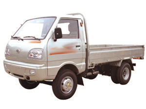
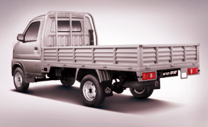
Ex. 1. In this lab we will create a 3D object in Blender representing a truck. Here are a couple of image we'll (loosely) use as models:
|
|
|
Boot your computer on MacOS. Open Blender. You will see a dialog. Click anywhere in the window to close it. You should see the starting scene containing a cube. Save if as truck.blend and save it again from time to time.
Use the scroll button to zoom in and out. Use the scroll with shift and then with ctrl to move the scene up-down and left-right. Use the NumPad keys 4, 6, 8, 2 to rotate the scene.
Use the NumPad keys 7, 9, 1, and 3 to switch to the standard views. Use NumPad 5 in either view to switch from Perspective projection to Ortho and back. Note the 3 axes in colors red, green, and blue, and how they are each aligned in the different views.
Finally, use NumPad 0 to go back to the initial camera view and NumPad 5 to switch to Perspective view.
These views can also be accessed from the View menu (bottom left of the screen).
Let's draw the wheels of the truck using a torus object. We will build the truck facing towards the front view. The truck's wheels will have to be vertically aligned and with the diameter circle situated in the zy plane (left / right). However, the torus will be constructed by default with the diameter circle in the xy plane, so we will have to rotate it.
Let's start from the Top / Ortho view. Click on the window below the cube to set the starting anchor point for the torus. Click on the Create tab on the upper left side of the window and then on Torus. Move the mouse pointer away from torus, then hit the key s to scale it. Reduce its size by moving the mouse closer so that it's a bit smaller than the cube in diameter. Left-click when you reached the desired size for the object.
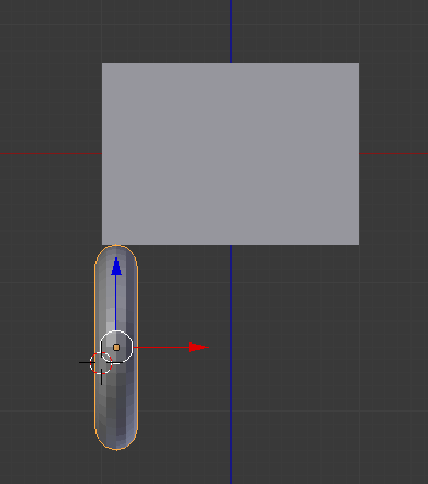
In order to bring the wheel to the right orientation, we need to rotate it by 90o around the y axis. For this, switch to the Front Ortho view. With the mouse pointer well away from the wheel, hit the key r to rotate. Move the mouse until the wheel is vertical, then left-click to complete the rotation.
Let's make the cube itself the part of the truck's cabin that starts above the wheel and ends just below the window.The shape is almost right, but it's a bit tall. Still in the Front Ortho view, right-click on the cube to select it. We want to scale it but only along the vertical axis, which here is z. Hit s to scale the cube, and then z to restrain the scale to this axis. Mouse the mouse down until the height of the cabin looks about right.
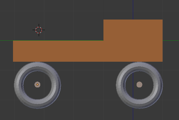
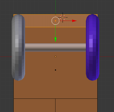
Right-click on the wheel to select it, then use the blue and red
arrows on it to drag it until it is right below the cabin vertically
and sticking out of it a little horizontally on the left. Here is a
screen shot of what you might have so far:
Before making more wheels, let's color this one. On the right side of the screen, below the list of objects in the scene, there is a small toolbar with many buttons. Click on the Material one in it. With the torus selected, click on + New. Click on the white area below Diffuse and set the color as dark blue. To see the effect, locate a white sphere menu next to Object Mode. Click on it and select Rendered. You should see the wheel as very dark blue. We will need more light sources to see it better, but it should give you an idea that the color was applied. Switch back to Solid in the same menu.
Let's make sure that the wheel is properly aligned on y. Switch to the Left Ortho view, then drag the green arrow on the wheel to place it under the cabin aligned on the right side with it.
Let's create a second wheel. Use Ctrl-c and Ctrl-v to copy and paste the wheel, then drag on the red arrow to move it along the x axis to the other side of the cabin. Now to make sure that the wheels are perfectly symmetrical, in the toolbar that currently shows the Material, click on the Object button and look under Transformation at the x component (the top value) of Location. If the second wheel doesn't have a color applied to it, click on Material and select the material you created for the first wheel.
Let's add an axle between the two wheels. Click on a point in between the wheels for the anchor point, then click on Cylinder in the Create toolbar. Look at the bottom left side of the window where we have some parameters for the new object. Set the radius to 0.1. The others can be left as the default. Then rotate the cylinder to be aligned horizontally and move it to connect the wheels. Set a light gray color for this object. Hit a to deselect the object.
Set the color that you want for the cabin. Then let's create the trunk area, so that we have a reference for the second set of wheels.
Switch the view to Back Ortho. We want to divide the back face in two first, and then extrude it afterwards.
Hit a to deselect the object. At the bottom where you see Object Mode, click on it and select Edit mode. Then further to the right of that there are 3 buttons shaped like small cubes that allow you to choose the Vertex, Edge, or Face selection mode. Click on the Face one. Then in the top left toolbar, click on the Tools tab. Click on Subdivide to cut it in two on both sides.
To extrude part of this face, first deselect everything (a), then right-click on the two bottom faces just created while holding the shift. Switch the view to Left Ortho, then hit e for Extrude and drag the face towards the left for a length a bit longer than the cabin. Left-click to set it in place.
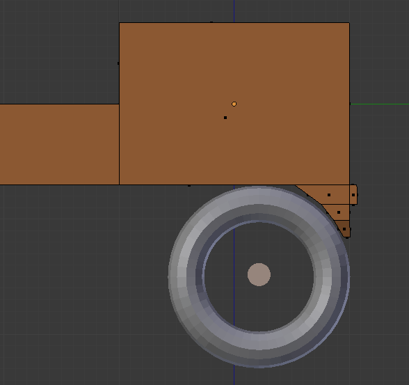
Let's copy the two front wheels and the axle to the back of the
truck. Switch from Edit Mode back to Object
Mode. Hit a to deselect the truck body, then
hit b to select all the objects bounded by a box. Click
somewhere below and to the left of the wheels+axle group, then drag
the mouse to the other side. If the body of the truck was also
selected, then shift-right-click on it to deselect it. Use copy-paste
to create a copy of these objects, then drag the green arrow towards
the left to place them at the back of the truck. Here is what your
truck might look like now:
Select the top face that you created. Go back to the Left Ortho view, then hit e to extrude the face. Drag it down a little, left-click to set it, scale it over y and translate it over y to align it with the front of the truck. You can repeat this a couple of times if you want more detail.
Switch to the Front Ortho view. Switch to Edit Mode -
Face and select the face on the from that you obtained by
extruding the bottom face in the previous operation. Switch
to Left Ortho view and extrude this face a little towards the
right to create a bumper. Here is what the result might be:
Let's create the top of the cabin, including the windows. Switch to the top view and select the top face of the cabin (edit mode, face). Switch to the left view and extrude this face for long enough to have the windows. After you click to set the extruded face, scale it down a little.
In Edit Mode - Face, select the top face of the cabin, where we want to create a window. Click on Inset faces and move the mouse down a little to the size of the window. Left click to set it. Then hit the delete key and delete the face. Repeat the procedure for the 3 other faces.
Select the top two faces of the trunk (which should be hollow) and delete them.
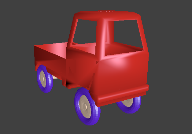
To see what the rendered image will look like, from the menu to the
right of the Object Mode select Rendered. In object mode,
click on Tools and then on Smooth
under Shading. You may have to add some more light sources
for the object to look nice. You can also click on Word in the toolbar
on the right side of the window and increase the ambient color a
little bit. Here is an example of the rendered scene:
On your own: add any other decoration that you want to the truck.
Save your file. From the Render menu choose Render Image. Then from the Image menu at the bottom, choose Save as image and save it to the save folder as truck.jpg. To go back to the edit mode, at the bottom on the left, click on the icon to the left of View and choose 3D View.
Upload to Canvas: the Blender file and the PNG file.